
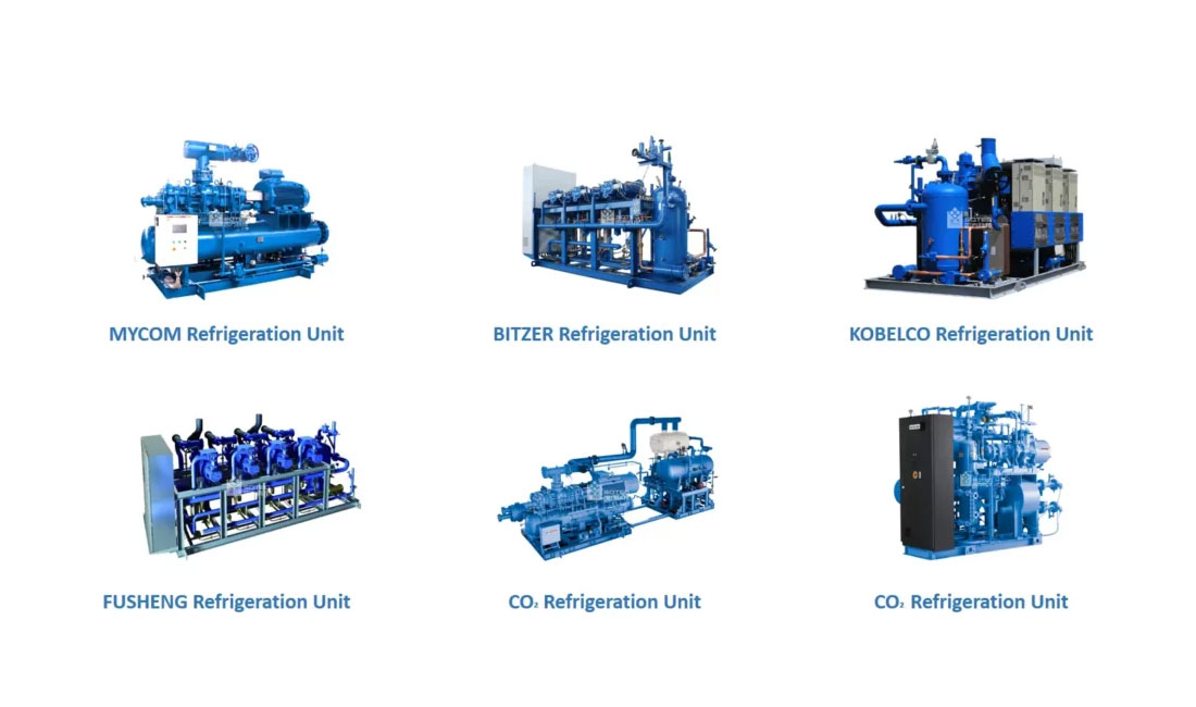
A cascade refrigeration system uses two or more separate cooling loops linked by a cascade heat exchanger. This design helps cold storage, vaccine storage, and process cooling reach very low temperatures when a single-stage system cannot work efficiently. In a cascade refrigeration system diagram, the high-temperature loop removes heat from the low-temperature loop, while each loop uses a refrigerant suited to its own temperature range.
Based on cold-chain engineering and industrial refrigeration project experience, this guide explains the system in simple steps. It covers the high-temperature circuit, low-temperature circuit, compressors, expansion valves, cascade heat exchanger, refrigerant pairs such as NH₃/CO₂, key applications, sizing factors, startup order, and maintenance needs.
What Is a Cascade Refrigeration System?
A cascade refrigeration system is a low-temperature cooling architecture that links two or more independent vapor-compression cycles through a shared heat exchanger. Each cycle runs a different refrigerant chosen for its working range, allowing the combined system to reach temperatures from –40°C down to below –80°C in standard industrial designs — and as low as –160°C in specialized multi-stage configurations used for gas liquefaction. The two-stage variant that powers most food freezing and cold-storage plants typically operates in the –40°C to –80°C band.
The “cascade” name reflects the way heat is handed down from one loop to the next, like water falling between basins. Each loop does only the work it does well, and the architecture sidesteps the physical limits that constrain any single refrigerant.
Why Can’t a Single-Stage System Reach Ultra-Low Temperatures?
A single refrigerant loses efficiency below –40°C because its pressure ratio becomes too high, its discharge temperature damages the compressor, and its suction pressure drops into vacuum. Cascading two refrigerants — each optimized for its own temperature window — eliminates these three failure modes at once.
The deeper the target temperature, the more punishing these effects become. Below roughly –50°C, even a two-stage compression machine using one refrigerant struggles to deliver acceptable coefficient of performance (COP). Switching refrigerants between stages is the only practical way forward.
How Does It Compare to Single-Stage and Two-Stage Compression?
Before looking inside the cycle, it helps to see where cascade architecture sits among the alternatives. Single-stage systems top out near –40°C. Two-stage compression with one refrigerant extends to roughly –50°C. Cascade architectures reach –80°C and below by switching refrigerants between stages, trading higher capital cost for ultra-low-temperature capability and a meaningfully better COP at deep temperatures.
The table below shows when each architecture is the right tool:
| Architecture | Practical Limit | Relative CapEx | Best For |
| Single-stage | ~ –40°C | Low | Standard cold rooms, chillers |
| Two-stage compression | ~ –50°C | Medium | Blast freezers, mid-range ULT |
| Cascade | –40°C to –160°C | High | IQF lines, vaccine storage, gas liquefaction |
Once the target temperature drops below –50°C, cascade stops being one option among three — it becomes the only option that works. The rest of this guide explains what’s happening inside that architecture.
How Does a Cascade Refrigeration Cycle Actually Work?
Two sealed loops run in parallel. The high-temperature (HT) loop rejects heat to ambient air or water. The low-temperature (LT) loop absorbs heat from the cooled space. A cascade heat exchanger thermally links them — acting as the evaporator for the upper loop and the condenser for the lower loop simultaneously.
What happens in the high-temperature circuit?
The HT loop uses a conventional refrigerant such as R-404A, R-134a, or ammonia. Its compressor draws vapor from the cascade heat exchanger, raises the pressure, and pushes it to the ambient condenser, where heat is dumped to outside air or cooling water. The liquid then expands back into the cascade heat exchanger and evaporates, pulling heat from the LT loop.
What happens in the low-temperature circuit?
The LT loop uses a refrigerant suited for very cold service — R-23, R-508B, or CO₂ are common choices. Its evaporator sits inside the cooled space, absorbing heat from products or air. The vapor is then compressed and condensed inside the cascade heat exchanger, where the HT refrigerant carries the heat away.
What role does the cascade heat exchanger play?
It is the thermal bridge that makes the entire architecture possible. The HT side evaporates in it; the LT side condenses in it. Designers typically allow a 5°C to 10°C approach temperature between the two loops — small enough to preserve efficiency, large enough to keep the heat exchanger compact.
How do you read the P-h and T-s diagrams of this cycle?
On a pressure-enthalpy (P-h) diagram, the cascade cycle appears as two stacked loops with a shared horizontal band where the HT evaporation pressure overlaps the LT condensation pressure. On a temperature-entropy (T-s) diagram, the same overlap shows as a thermal handshake between the two cycles at the cascade temperature.
What Components Make Up the System?
The architecture requires two compressors, two expansion valves, two evaporators, one ambient condenser, and one cascade heat exchanger that bridges the loops. Auxiliary parts include oil separators, an LT-side expansion vessel for shutdown pressure protection, and dedicated control logic that sequences the two loops.
The table below summarizes the function of each major component:
| Component | Located In | Function |
| HT compressor | High-temp loop | Lifts vapor pressure for ambient heat rejection |
| Ambient condenser | High-temp loop | Releases heat to air or water |
| Cascade heat exchanger | Both loops | HT evaporator + LT condenser |
| LT compressor | Low-temp loop | Compresses cold-side refrigerant |
| LT evaporator | Low-temp loop | Absorbs heat from the cooled space |
| Expansion valves (×2) | Each loop | Drops pressure before evaporation |
| Expansion vessel | Low-temp loop | Absorbs pressure rise during shutdown |
Plate-type or shell-and-tube — which cascade heat exchanger is right?
Plate heat exchangers offer a high heat-transfer coefficient and a compact footprint, making them the default choice for capacities up to a few hundred kilowatts. Shell-and-tube units handle larger industrial duties and tolerate fouling better. Plate types require a refrigerant distributor at the HT inlet to ensure even flow across the channels.
Why does the low-temperature side need an expansion vessel?
When the system shuts down, the LT refrigerant warms toward ambient temperature. Because it is designed for very cold service, its saturation pressure rises sharply. The expansion vessel absorbs this pressure surge and protects piping and components from rupture. Industrial-grade heat exchangers and refrigeration components used in cascade systems are sized specifically for this duty.
What Refrigerant Pairs Are Used and Why?
Common pairings are R-404A/R-23, NH₃/CO₂, and R-134a/R-508B. The high-temperature side uses a standard refrigerant; the low-temperature side uses one that stays liquid and efficient below –50°C. Selection now favors low-GWP fluids under EU F-gas rules and similar regulations worldwide.
The most widely deployed pairings and their characteristics:
| HT Refrigerant | LT Refrigerant | Typical Temp Range | Notes |
| R-404A | R-23 | –40°C to –80°C | Legacy standard; high GWP |
| Ammonia (NH₃) | CO₂ (R-744) | –40°C to –55°C | Industrial favorite; very low GWP |
| R-134a | R-508B | –50°C to –80°C | ULT freezers, lab use |
| R-452A | R-23 or CO₂ | –40°C to –75°C | EU F-gas-compliant replacement |
Why is NH₃/CO₂ becoming the industrial standard?
The pairing combines two natural refrigerants with negligible global warming potential. Ammonia delivers excellent thermodynamic performance on the high side, and CO₂ behaves well at low temperatures and high pressures. For new cold storage and food processing plants, regulators and operators increasingly treat this combination as the default specification.
What Are the Operational Advantages and Trade-Offs?
Cascade systems deliver real engineering benefits that go beyond temperature reach. The main advantages and trade-offs are:
- Reaches temperatures no single refrigerant can practically deliver
- Lower compression ratio per stage, which raises volumetric efficiency
- Smaller LT-side compressor displacement than an equivalent two-stage machine
- Lower discharge temperature, which extends compressor and oil life
- Positive suction pressure on both loops, preventing air ingress and moisture
- Higher capital cost and a larger plant footprint
- More complex commissioning and controls
- Requires skilled operators and a disciplined maintenance program
Where Is Cascade Refrigeration System Used in Industry?
Any process that requires stable temperatures below –40°C is a candidate for a cascade design. In practice, the architecture has spread across food freezing, cold-chain logistics, pharmaceutical storage, and large-scale gas liquefaction — with each application pushing the design in a slightly different direction.
The core industrial application is food freezing and cold storage. Square Technology’s systèmes de réfrigération are built for exactly this domain: cascade architectures power the spiral, tunnel, and plate freezers that lock in product quality at –35°C to –40°C across seafood, meat, poultry, bakery, and ready-meal production lines. These installations typically run standard two-stage NH₃/CO₂ cascades, and increasingly substitute CO₂-sublimation variants below –50°C to cut the refrigerant’s environmental footprint.
Beyond food, the same thermodynamic principles appear in adjacent industries. Pharmaceutical cold chains use cascade systems for vaccine storage at –70°C. LNG terminals and chemical plants push the architecture furthest of all: three-stage cascades using propane, ethane, and methane can liquefy natural gas down to approximately –162°C, where no standard two-stage design can follow. These applications share the same underlying cycle, but each requires refrigerant pairings, compressor choices, and plant integration that are specific to the industry.
How Do You Size and Specify a System for Your Plant?
Sizing starts with the cooling load at the target temperature, then sets the cascade crossover point — typically –30°C to –40°C. The refrigerant pair, compressor types, and approach temperature on the cascade heat exchanger follow from that load and that target. Ambient conditions and refrigerant regulations finalize the specification.
A practical specification workflow looks like this:
- Define the cooled-space temperature and total heat load in kilowatts
- Select the cascade crossover temperature (usually 30°C to 40°C above the target)
- Choose the HT and LT refrigerant pair based on regulation, safety, and GWP
- Size both compressors, allowing margin for pull-down and defrost cycles
- Select the cascade heat exchanger with a 5°C to 10°C approach temperature
- Specify oil management, expansion vessel capacity, and control sequencing
How Should the System Be Started, Operated, and Maintained?
Operators should always start the high-temperature side first, then the low-temperature side; reverse the order on shutdown. They should keep the LT return-gas temperature above –60°C, monitor superheat on both circuits, manage LT-side oil return carefully, and inspect the expansion vessel and refrigerant charge annually.
This sequencing matters because the cascade heat exchanger must already be cold before the LT compressor starts pushing refrigerant into it; otherwise the LT discharge pressure spikes and the compressor trips on safety. On shutdown, stopping the LT loop first lets the HT loop pull residual heat out of the cascade heat exchanger before it too goes offline.
FAQs
What is the lowest temperature a cascade refrigeration system can reach?
A standard two-stage cascade reaches around –80°C. Three-stage cascades used in LNG liquefaction can cool natural gas down to approximately –162°C, which represents the practical lower limit for industrial cascade designs.
What is the difference between cascade and two-stage compression?
Two-stage compression uses one refrigerant through two compression steps. Cascade uses two different refrigerants in two separate loops, linked by a heat exchanger. Cascade reaches much colder temperatures with better efficiency.
Why must the high-temperature side start before the low-temperature side?
The cascade heat exchanger must be pre-cooled by the HT loop before the LT compressor runs. Otherwise LT discharge pressure spikes immediately and trips the compressor on safety.
Is an NH₃/CO₂ cascade safe for food processing plants?
Yes, when designed correctly. Ammonia stays in a confined machine room with leak detection, while CO₂ circulates through the cold spaces. This layout is now the default for new large-scale food freezing facilities.
How much does a cascade refrigeration system cost?
Industrial installations range from tens of thousands of dollars for small packaged units to multi-million-dollar systems for full IQF freezing lines and large cold-storage plants. Detailed pricing requires a load-based quote.